This is a more technical look at the bomb defusing puzzle discussed in “Defuse The Bomb” Puzzle Game with the Scouts.
Initial Designs – Use a PIC Microcontroller
My first plan was to use an 8 pin PIC Microcontroller. This would have been adequate for a simple project like this. Sadly I found that when I upgraded the PIC Development software my PicKit3 programmer was no longer supported. I was unable to downgrade the software, so was stuck (unless I could find something running on Linux to access it).
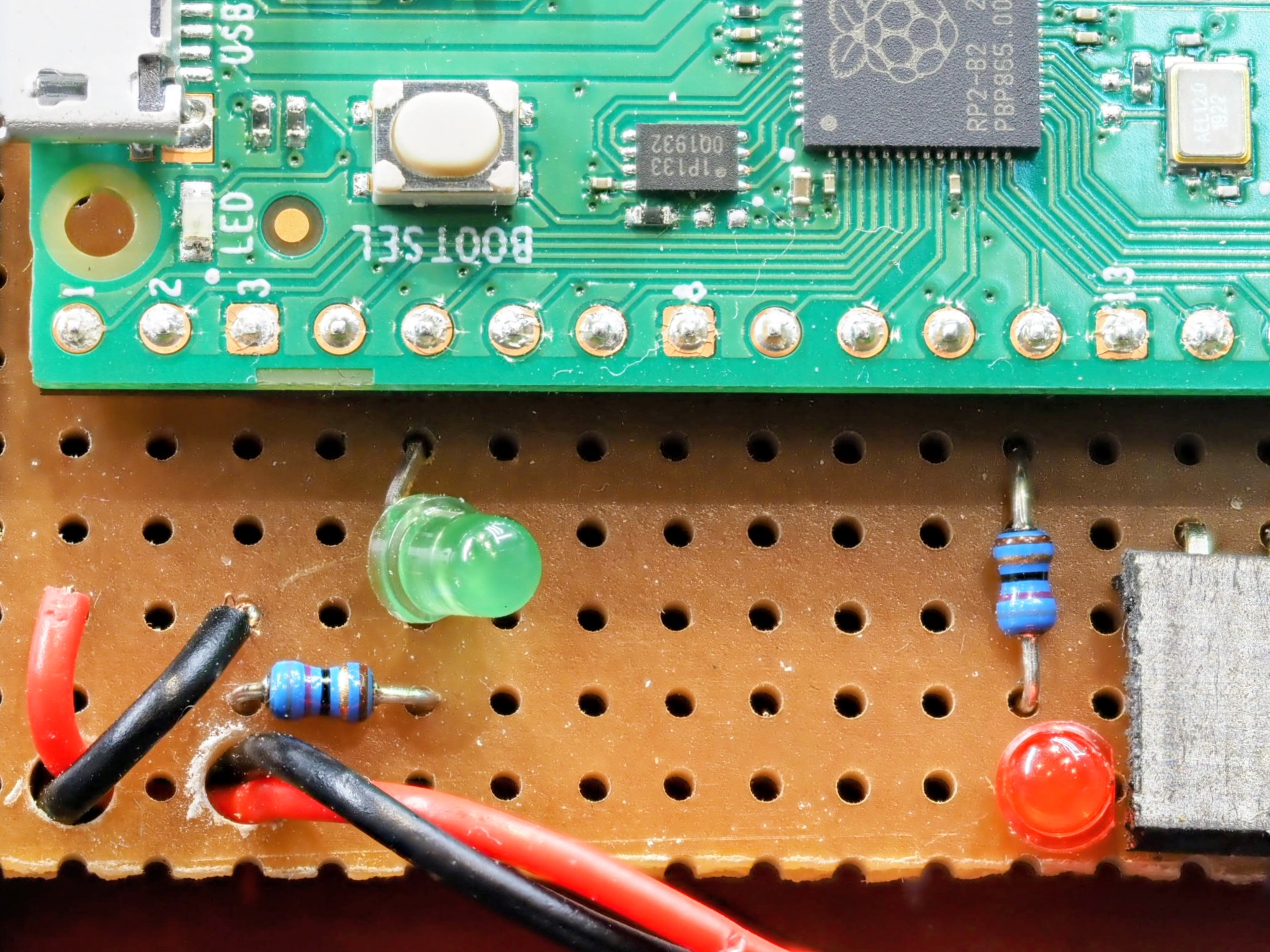
I had a Raspberry Pi Pico to hand, and in retrospect I believe it was the better solution. It looks the part more and its increased amount of GPIO meant I could add more features. At £4 it’s not much more for a hobbyist than working with PICs and certainly dissuades me from spending over £100 to upgrade my programmer to work with Microchip’s latest software!
The PIC has excellent low power modes for use in battery equipment with the battery permanently connected, but this is not that kind of project. Current draw for this project was about 30 to 40mA (subject to smoothing on the display of my bench power supply).
PIC Pin Multiplexing
It’s worth mentioning how I was going to multiplex 5 wires, an LED and a buzzer on only 6 available pins of the PIC16.
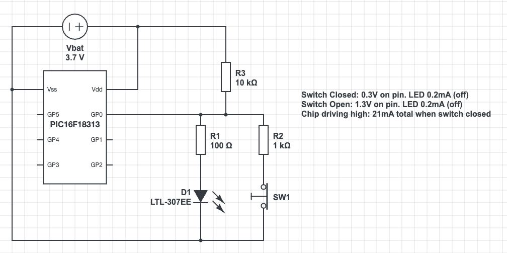
The PIC can light the LED by sending the pin high. It can set the pin to input and read the voltage to detect the position of the switch. The voltages would be fine for a transistor input, but fall outside the sense ranges for a Schmidt Trigger input. The high voltage of 1.3V is in the unknown zone in the middle so this would need the PIC to run the input in analog mode. That will increase the complexity of the programming.
I could try adjusting resistor values. I’d also have to consider the need to switch rapidly between input and output modes to achieve the logic I achieved with the Raspberry Pi. It would have been a lot of effort, especially in comparison with the ease of programming in micro-python!
Raspberry Pi Inputs and Outputs
The Rasberry Pi was simple in comparison with the PIC. It has so many GPIO pins that I could choose pins near to where I wanted my components. The puzzle wires connect between the pin and ground. A “weak pullup” setting is used to provide the resistor to Vdd. This input risks noise with a floating wire, perhaps part of the issue I had with debouncing when using wire cutters on the wires. It is simple though!
Output is the standard resistor/LED circuit. I used 68 ohm resistors I had in my spare parts kit. In retrospect this is too small. The Pi output is rated at only a few milliamps with total draw from the system power supply around 50mA. Five LEDs all on at 15mA each would exceed this. I used pulse width modulation in software to both dim the LEDs and reduce the current draw. A larger series resistor would have made this design safer. It seems that the Python library I use is using hardware PWM or some kind of PWM firmware that survives application pause from the development environment, so I’m not left with suddenly bright LEDs if the program stops for any reason.
The Software
The software is in a single large file. This made working on it in the Thonny development environment easier. It was written in limited time, so less time was spent on modularisation than a professional software project would require.
The software is based on a state machine. The variable “state” is in fact the input, though the wait routines mean that its value is known as we transition between states in code. The states in code are the main loop, the onLose() and onWin() functions, and the wait_for_reset() function.
# This is the answer - the wire GPIOs in order that they must be cut
BUTTON_GPIOS = [WHITE,GREEN,RED,YELLOW,BLACK]

# Initialise the Button objects to represent the puzzle wires
wires = [Button(pin, bounce_time=DEBOUNCE) for pin in BUTTON_GPIOS]
WINNING_STATE = 2 ** len(BUTTON_GPIOS) - 1

# Return the button state in terms of the actual logic levels on the
# pins as a bit field. The least significant bit is the first wire to
# be cut. When all wires are connected this will be 0. When all are
# cut it will be WINNING_STATE which is 31 for our 5 wire system.
def get_button_state():
    raw = sum(wire.value * 2**index for (index,wire) in enumerate(wires))
return raw ^ WINNING_STATEState is a bitfield in which the bits represent the log levels of the wires in order that they have to be cut. This allows the calculation of next valid state to be made very easily and greatly simplifies the code! (I’d asked Gemini to try this and it made something a lot more complex). We can see from the code above that the system can handle an arbitrary number of puzzle wires.
def next_state(state):
    return (state << 1) | 1

def prior_state(state):
    return (state >> 1)

def is_winning_state(state):
    return state & WINNING_STATE == WINNING_STATE

def is_reset_state(state):
return state == 0The main loop is incredibly simple. I added the ability to move backwards through the states in case of bounce/noise induced while using wire cutters on the wires.
while True:
    buzzer.value(0)
    print("Initialsing....")
    state = wait_for_reset(state)
    print("Initialised")
    expected = next_state(RESET_STATE)
    state = wait_for_change(RESET_STATE)
    backward_state = RESET_STATE     # Added ability to step backwards to improve debounce
    pico_led.blink()
    while state != RESET_STATE:
        if is_winning_state(state):
            state = on_win(state)
        elif state == backward_state or state == expected:
            expected = next_state(state)
            backward_state = prior_state(state)
            state = wait_for_change(state)
        else:
state = on_lose(state)The win and lose routines are very similar. Sleep a little to allow signals to really stabilise. Set the buzzer on or off as needed. The lose routine stops the buzzer as soon as any change is made. This allows the operator to silence the buzzer easily.
def on_lose(state):
    buzzer.value(1)
    print("BOOOOOOM")
    pico_led.on()
    sleep(1)    # Added more pause for debounce
    state = wait_for_change(state)
    buzzer.value(0)
    state = wait_for_reset(state)
return statePolling – Background Tasks
The Morse Code and blinked LEDs appear as background tasks, yet the Pico cannot multitask and I didn’t see any obvious signs of the timers and features of RTOS on the ESP32. (It may be there, but I was writing this quickly in a cafe).
This is achieved using timestamps and the ticks_ms(), ticks_diff() and ticks_add() functions. The main polling loops are the wait_for_change() and wait_for_reset() functions. These both take the state on input and return the state on output, a general pattern for any state changing code (on_win() and on_lose() also).
def wait_for_change(state):
    new_state = state
    while new_state == state:
        new_state = get_button_state()
        blinkenlicht_poll(new_state)
        if(state & WINNING_STATE != WINNING_STATE):
            morse_step()
return new_stateEach flashing LED has its own timer, so blinkenlicht_poll() polls all of the LEDs having worked out which ones should be enabled.
# In class RandomlyBlinkingLED
    def poll(self):
        now = ticks_ms()
        if ticks_diff(now, self.next_poll) > 0:
            self.value = 1 - self.value
            self._output()
            self.next_poll = ticks_add(now, self._calc_delay())

# This is called in a loop
def blinkenlicht_poll(state):
    for index, led in enumerate(leds):
        flag = 2 ** index
        led.enable(state & flag != flag)
led.poll()Morse Code Routines
The technique to encode Morse was created for smaller microcontrollers such as the PIC. They allow me to store an Morse letter as a single byte. I’d wondered if I could fit two characters per byte, but some are too long when you start to include numbers and symbols.
Consider the character C. This is -.-. (dah-dit-dah-dit). If I encode this in binary with dah as 1 and dit as 0 it is 1010. Similarly A is 01 and L is 0100. How can I store this? The answer is to pack it out to a byte, but set the remaining bits to the opposite of the last bit in the character. C becomes 10101111. I then turn this around to be Least Significant Bit first. I’m going to need to shift bits and an Arithmetic Shift Right preserves the value of the topmost bit.
So playing through the letter C:
| Value | Action |
11110101 | LSB is 1. Play dah and shift right |
11111010 | LSB is 0. Play dit and shift right |
11111101 | LSB is 1. Play dah and shift right |
11111110 | LSB is 0. Play dit and shift right |
11111111 | All bits are the same. Stop. |
For A:
00000010 | LSB is 0. Play dit and shift right |
00000001 | LSB is 1. Play dah and shift right |
00000000 | All bits are the same. Stop. |
The Morse Step routine implements the polling loop and state transition logic for the Morse Code system. A professional project would split this method up. The flow is:
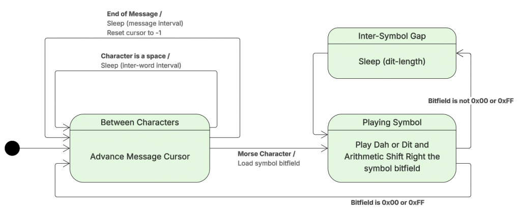
The code that implements the state changes:
def morse_step():
    global morseState
    global morseCursor
    global morseCurrentCharacter

    if ticks_diff(ticks_ms(), morseNextAlarm) < 0:
        return

    if morseState == MORSE_STATE_INTER_CHARACTER:
        morseCursor = morseCursor + 1
        if morseCursor >= len(MORSE_CLUE):
            morseCursor = -1
            morse_sleep(MORSE_INTER_MESSAGE_LENGTH)
            return
        currentLetter = MORSE_CLUE[morseCursor]
        if currentLetter == ' ':
            morse_led_off()
            morse_sleep(MORSE_INTER_WORD_LENGTH)
            return
        else:
            ordinal = ord(currentLetter.upper()) - ord('A')
            morseCurrentCharacter = MORSE[ordinal]
            morse_play_current_symbol()
            return
    elif morseState == MORSE_STATE_INTER_SYMBOL:
        morse_shift_bits()
        if morseCurrentCharacter == 0 or morseCurrentCharacter == 0xFF:
            morseState = MORSE_STATE_INTER_CHARACTER
            morse_sleep(MORSE_INTER_CHARACTER_LENGTH) # On top of after symbol
            return
        else:
            morse_play_current_symbol()
            return
    else:
        morseState = MORSE_STATE_INTER_SYMBOL
        morse_led_off()
        morse_sleep(MORSE_DIT_LENGTH)
Leave a Reply