I’ve been asked how somebody without electronics experience could implement the “Defuse The Bomb” Puzzle Game with the Scouts. This cuold also be attempted by the Scouts as part of their Digital Maker Stage 3 badge.
The Bare Minimum – Breadboard
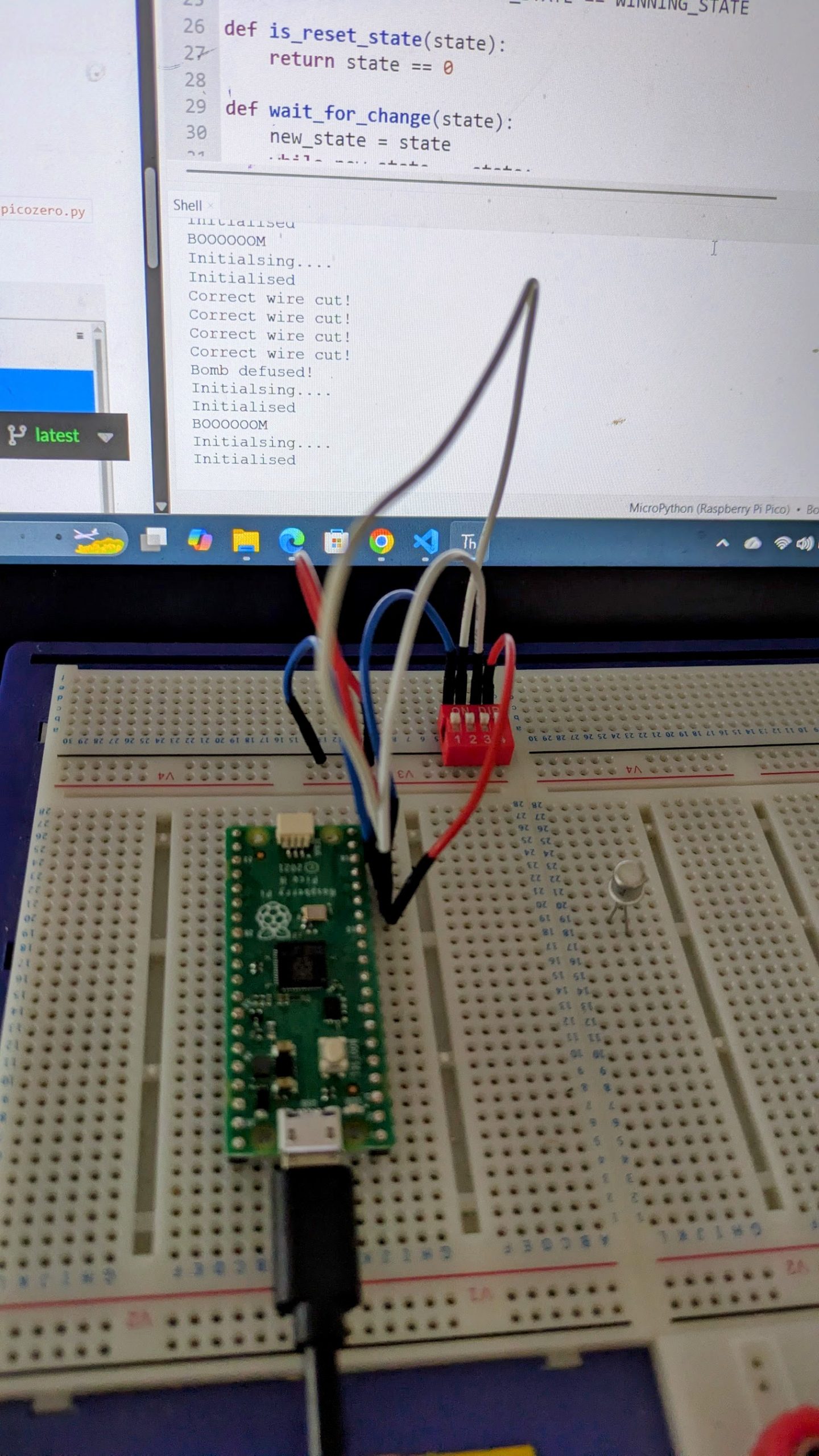
The bare minimum to get this working, without soldering, is a Raspberry Pi PICO with headers and electronics breadboard. You’ll also need a USB cable for the Pico (mine takes Micro-B type) and a computer running the Thonny development environment.
The software is available on GIT. You can copy and paste this into Thonny and ask it to save it to the Pico as main.py. You may also need to install the pico python library code onto the pi. If I remember correctly Thonny will ask you if you want to do this automatically.
If you run (green play icon at the top) the software you’ll see it output “Initialising….” in the window at the bottom and nothing else until you wire up the peripherals.
Using the breadboard
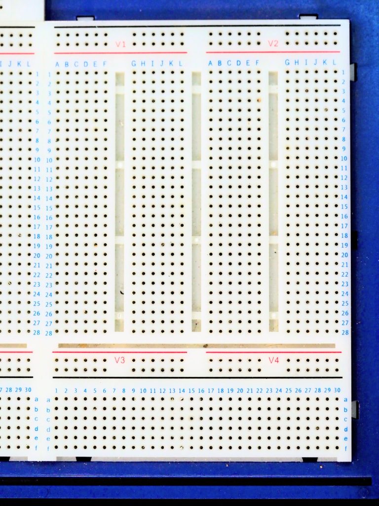
The breadboard is a handy way to develop electronics. You just plug components in and they connect. Most breadboards are like the top section on mine (above the black line). Tracks run across the board, and are numbered 1 to 28 in the main section here. The physical gaps in the board are breaks in the tracks. These are for use with integrated circuits like the Pico. You need to place the Pico facing along one of these gaps and straddling it so that the pins on each side are not connected together.
My Pico with the headers is currently soldered to my defuse puzzle, so for this photo I’ve found a Pi Pico-W I’d used in a temperature and humidity sensing project. Ignore the wires soldered to it – these are the sensor.
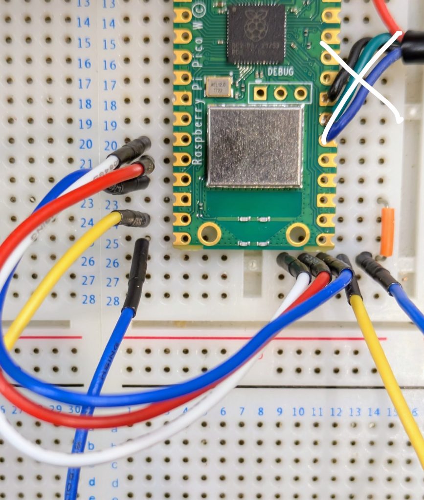
The short orange jumper links one of the ground pins (they’re slightly square if you look carefully) on the Pico to the right hand half ot track 26 on my breadboard. I have one of these kits which I’ve had for a long time. Was it really that expensive when I bought it? The flexible wires are something like these.
Once you have these wires in you can perform the puzzle using the output on the computer screen to indicate success and watch the LED built in to the Pico for the Morse message. It will go out when the puzzle is defused, and stay on if the user fails.
Buzzer
Next to add is the buzzer. I’ve used a cheap piezo buzzer I bought from Amazon for the Scouts Communicator Badge. It is rated at 3V to 25V and works well enough at the 3.3V provided by the Pico. Connect positive to pin 1 in the top left hand corner of the Pico. Negative goes to the nearest ground pin which is pin 3.
LEDs
If you want to add in extra LEDs you’ll need an LED and a resistor.
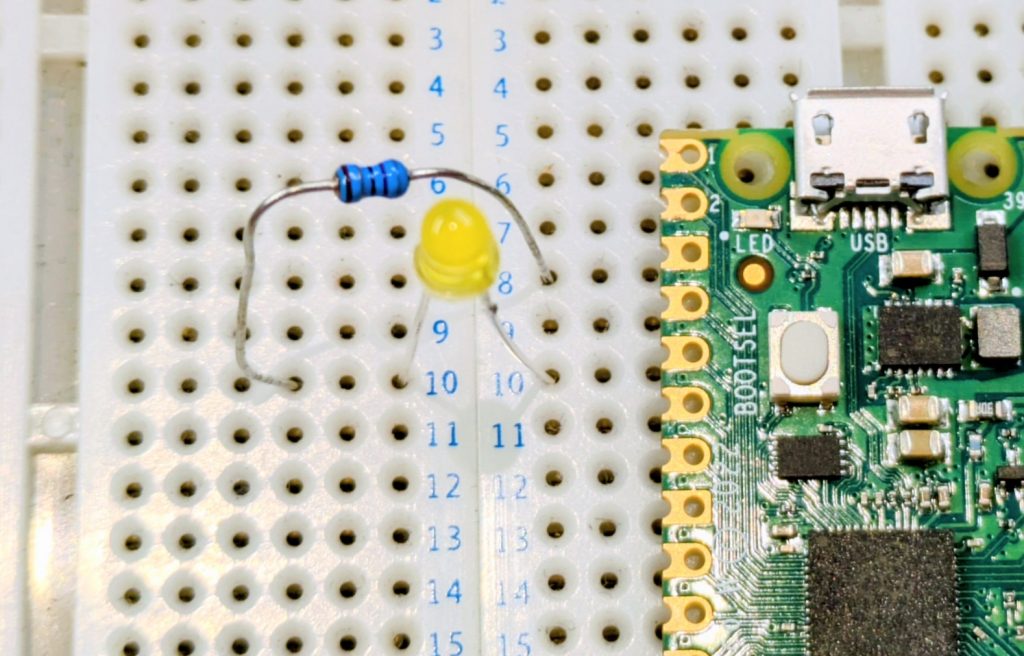
Again, I’ve laid the Pico against the board as this is not my version with the headers. The long leg of the LED is on the right in this image, towards the pin (pin 5 on the Pico) which is +3.3V to turn it on. The resistor connects between the short leg (-ve) to the nearest ground pin (pin 3). Notice how I’ve used a gap in the breadboard to break the track. If I didn’t have a suitable gap then I’d have to use jumper wires to link to a spare track on the board.
The Raspberry Pi datasheet has a diagram on page 4 which tells you which physical pin corresponds to which GPIO number mentioned in the code at the top. You can use this to find the physical pins for the five LEDs, or change them if you wish.
Calculating LED resistors
A 100 ohm resistor is fine for this, but note the comment in the code about power management. 5 LEDs at full brightness would exceed the power capability of the board. You could use larger resistors to reduce current, low current LEDs (with larger resistors), or as the software does use pulse width modulation to reduce power. This turns the LED on and off very quickly so that it spends most of its time off. If you want brighter LEDs or more power then you’ll need to use transistors to switch the higher loads.
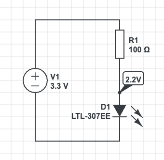
A typical LED has a voltage of 2.2V and requires 20mA to light fully. The Raspberry Pi can provide about 8mA if we don’t use the PWM code to dim the LED.
The voltage across the resistor is
The resistance from is . Choose the next highest standard resistor value which is
I’ve used a lower value resistor but had to compensate for this in software to reduce the current draw. If you use the larger resistor (safer) then you may need to adjust the value in software. Full brightness is 65535
# PWM is used to manage the current draw. We aim for 50mA Max Total
# across all LEDs in the system.
# The dimmer light is also less blinding when the user is trying to
# copy the Morse clue.
LED_ON_PWM_U16 = 3000Moving to Veroboard
If you want to make this permanent then you can build onto Veroboard. This is a prototyping technology. You’ll need to be able to solder. There are numerous tutorials online. You’ll also need to cut the tracks. I use a drill bit which I turn by hand to remove the copper. This is the under-side of my circuit board. I’ve drilled small holes to act as strain relief on the cables too.

Battery Connection
The circuit can run very well from a power bank plugged in to its USB socket. You’ll need to enable “Low Power Mode” on the power bank if yours has it, otherwise there is a chance it will switch off shortly after power on because the current drain from the circuit is too small for its load detection circuit.
The circuit can be powered from a battery. I’ve used a 3.7V lithium cell designed for use in devices and wired a connector for it on flying leads to the Vsys and GND pins on the right hand side of my board. Best check the data sheet for information about power supply suitability. Also use a cell with built in protection circuitry if using lithium chemistry cells. A short circuit would be incredibly dangerous without!
Other Links
My write-up of the evening is at “Defuse The Bomb” Puzzle Game with the Scouts
A more technical discussion of the code is at Technical Deep Dive on the Bomb Puzzle
Leave a Reply