Category: Scouts

  • Writing the Party-Bot

    Writing the Party-Bot

    This will be impressive if it works! Using Claude to write a party food organising bot on top of my wide-game-bot framework!

    I’ve extended the framework to allow a Game Type to choose the “command routing” taken by the system. It already had fixed command routers depending on player context, “Admin”, “Player”, “Idle” and “Anonymous”. Now I add a concept of a RoutePair which means that my wide games will go to “location-base-game/admin” and “location-based-game/player“. These remain the same, but I add a new “party/admin” and “party/player“.

    These routes both inherit the “always” route which allows for joining and leaving a game, and then implement only an AI Assistant. The assistant has tools to get the party menu and allow a player, er…., participant to specify what they are bringing.

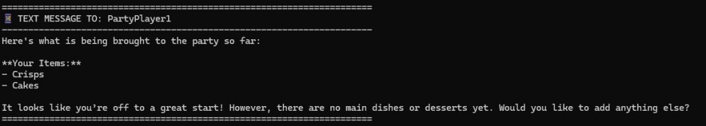
    Players Participants can only see their own food and that someone else is bringing crisps and nibbles. The game admin can see the entire menu alongside who is bringing what.

    This is a great thing about Strategy Pattern. I’ve just added a new Game Type Strategy which plays a very different game to anything I imagined when I started this project.

    Findings as I implement this

    Teams!

    The existing games are in teams. The architecture assumes that a player is part of a team and a team is in a game. This means that party participants also have to be in teams! This could work well. “The Smith Family” could have both parents contributing to the same food list. It also means that a participant chooses their display name. I was going to use their WhatsApp display name. The system uses AI to moderate these. I’ll have to have the AI moderate their food choices too!

    Other people’s ideas?

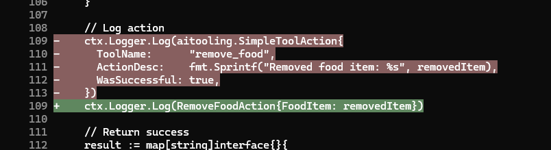
    I imagine other people are solving the problems I’m solving. I’ve never had a SimpleToolAction, but the idea here is interesting and maybe I can learn from it.

    I should have stuck to Stores

    I discussed store pattern in Experiments in Go – Three Tier Architecture in a WhatsApp Game-Bot and decided to move from a Store pattern with manual SQL to using Gorm directly in code. I’m learning now that I should have stuck to Stores, and will write up more on this later.

    Claude keeps looking for Stores. I don’t know if that’s from remains of documentation about the pattern in the codebase docs folder, or because everyone does Stores. The final architecture would be Stores with Gorm based store implementations but that will be a large refactor (oh no not again!). I’m finding the domain package is filling up with Store methods. I also want to be able to swap in things like a REDIS store for objects like the mementos used to track multi-step user conversations.

    A Prompt Injection Attack! (Sort of)

    I’d initially intented it not to be possible for participants to see who was bringing what. In retrospect this was an anti-feature. People are discussing this over WhatsApp in the Parents Channel. When I wrote the wide-game-bot I’d designed the player tools to make it impossible for the AI to do anything the player should not do or access information that the player cannot access. Claude’s rapidly written “list_food” tool returns the food items along with the name of the teams that bring them.

    I noticed this when a parent asked me to add a food item on their behalf. So I added specifically “Crisps (Eliot)”. The AI then started including team names for all of the other items in brackets when listing foodstuffs!

    So my food item was

    JSON
    {
       "food":"Crisps (Eliot)",
       "team":"Sparks and James"
     }

    Every other item was

    JSON
    {
      "food":"Drinks",
      "team":"The Smiths"
    }

    The AI formatted that one as “Drinks (The Smiths)“.

    It’s an easy bug to fix, but I’ve not fixed it because I think it’s actually a feature. If Claude had followed my original intent and prevented acccess then I’d have been tempted to add it in!

    My wide game players still cannot see whether territory is owned by any other teams before entering it and risking a penalty, or in the simple Score game they cannot see which bases have been claimed already.

    Conclusion

    I have a party-bot. It was developed very quickly, a few hours including refactoring the Game Strategy to allow complete user input routing override through the existing Command Router System and debugging.

    Testing the new bot as an admin using my Simulator test-harness
    Testing the bot using my simulator test-harness command.

    I have a lot of technical debt and a large TODO file to clean it all up.

    I’m about to test this all for real by sharing it with my Scout parents!

    Is Conversational AI the new User Interface?

    Using the live system!

    I’ve got used to it and find it natural. Will my users? That’s a big question. This could be crying out for a quick website solution, something which I may well add! Then I’ll have a web site and WhatsApp user interface to the same backend data which will be neat.

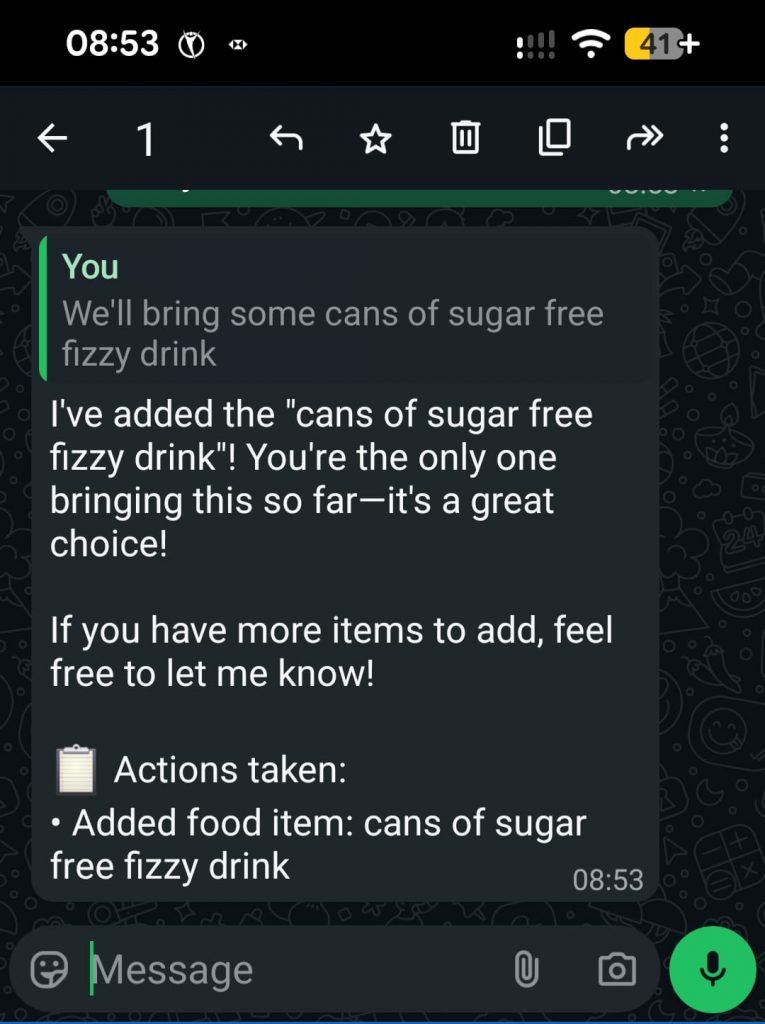
    I can imagine a world in which conversational UI is the norm. It seems full circle, back to the command line, but with voice recognition. “Hey – Party-Bot – We’re bringing cake!” – possible now if someone presses the “voice input” button on their phone.

    The web site would also have a place. This is a problem that just calls for tabular data and an “add row” button.

    References

    This is the AI Assistant supporting code from the project:
    https://github.com/m0rjc/goaitools

    I hope to publish the WhatsApp ingress and egress code when it is in some kind of shape to be shared. At the moment it has no egress rate limiting, which is a risk. The chance of me exceeding WhatsApp limits with a small party of Scout parents is low, so I take that risk.

  • Scouts “Defuse The Bomb” game – Shallow Dive

    Scouts “Defuse The Bomb” game – Shallow Dive

    I’ve been asked how somebody without electronics experience could implement the “Defuse The Bomb” Puzzle Game with the Scouts. This cuold also be attempted by the Scouts as part of their Digital Maker Stage 3 badge.

    The Bare Minimum – Breadboard

    The bare minimum to get this working, without soldering, is a Raspberry Pi PICO with headers and electronics breadboard. You’ll also need a USB cable for the Pico (mine takes Micro-B type) and a computer running the Thonny development environment.

    The software is available on GIT. You can copy and paste this into Thonny and ask it to save it to the Pico as main.py. You may also need to install the pico python library code onto the pi. If I remember correctly Thonny will ask you if you want to do this automatically.

    If you run (green play icon at the top) the software you’ll see it output “Initialising….” in the window at the bottom and nothing else until you wire up the peripherals.

    Using the breadboard

    Electronics prototyping breadboard

    The breadboard is a handy way to develop electronics. You just plug components in and they connect. Most breadboards are like the top section on mine (above the black line). Tracks run across the board, and are numbered 1 to 28 in the main section here. The physical gaps in the board are breaks in the tracks. These are for use with integrated circuits like the Pico. You need to place the Pico facing along one of these gaps and straddling it so that the pins on each side are not connected together.

    My Pico with the headers is currently soldered to my defuse puzzle, so for this photo I’ve found a Pi Pico-W I’d used in a temperature and humidity sensing project. Ignore the wires soldered to it – these are the sensor.

    The end of a Pi Pico held against breadboard with the puzzle wires shown

    The short orange jumper links one of the ground pins (they’re slightly square if you look carefully) on the Pico to the right hand half ot track 26 on my breadboard. I have one of these kits which I’ve had for a long time. Was it really that expensive when I bought it? The flexible wires are something like these.

    Once you have these wires in you can perform the puzzle using the output on the computer screen to indicate success and watch the LED built in to the Pico for the Morse message. It will go out when the puzzle is defused, and stay on if the user fails.

    Buzzer

    Next to add is the buzzer. I’ve used a cheap piezo buzzer I bought from Amazon for the Scouts Communicator Badge. It is rated at 3V to 25V and works well enough at the 3.3V provided by the Pico. Connect positive to pin 1 in the top left hand corner of the Pico. Negative goes to the nearest ground pin which is pin 3.

    LEDs

    If you want to add in extra LEDs you’ll need an LED and a resistor.

    LED and resistor shown in the correct place against a Pi Pico

    Again, I’ve laid the Pico against the board as this is not my version with the headers. The long leg of the LED is on the right in this image, towards the pin (pin 5 on the Pico) which is +3.3V to turn it on. The resistor connects between the short leg (-ve) to the nearest ground pin (pin 3). Notice how I’ve used a gap in the breadboard to break the track. If I didn’t have a suitable gap then I’d have to use jumper wires to link to a spare track on the board.

    The Raspberry Pi datasheet has a diagram on page 4 which tells you which physical pin corresponds to which GPIO number mentioned in the code at the top. You can use this to find the physical pins for the five LEDs, or change them if you wish.

    Calculating LED resistors

    A 100 ohm resistor is fine for this, but note the comment in the code about power management. 5 LEDs at full brightness would exceed the power capability of the board. You could use larger resistors to reduce current, low current LEDs (with larger resistors), or as the software does use pulse width modulation to reduce power. This turns the LED on and off very quickly so that it spends most of its time off. If you want brighter LEDs or more power then you’ll need to use transistors to switch the higher loads.

    A typical LED has a voltage of 2.2V and requires 20mA to light fully. The Raspberry Pi can provide about 8mA if we don’t use the PWM code to dim the LED.

    The voltage across the resistor is 3.3V2.2V=1.1V3.3\text{V} – 2.2\text{V} = 1.1\text{V}

    The resistance from R=V/IR = V/I is R=1.1/0.008=137.5ΩR = 1.1/0.008 = 137.5\Omega. Choose the next highest standard resistor value which is 140Ω140\Omega

    I’ve used a lower value resistor but had to compensate for this in software to reduce the current draw. If you use the larger resistor (safer) then you may need to adjust the value in software. Full brightness is 65535

    Python
    # PWM is used to manage the current draw. We aim for 50mA Max Total
    # across all LEDs in the system.
    # The dimmer light is also less blinding when the user is trying to
    # copy the Morse clue.
    LED_ON_PWM_U16 = 3000

    Moving to Veroboard

    If you want to make this permanent then you can build onto Veroboard. This is a prototyping technology. You’ll need to be able to solder. There are numerous tutorials online. You’ll also need to cut the tracks. I use a drill bit which I turn by hand to remove the copper. This is the under-side of my circuit board. I’ve drilled small holes to act as strain relief on the cables too.

    Battery Connection

    The circuit can run very well from a power bank plugged in to its USB socket. You’ll need to enable “Low Power Mode” on the power bank if yours has it, otherwise there is a chance it will switch off shortly after power on because the current drain from the circuit is too small for its load detection circuit.

    The circuit can be powered from a battery. I’ve used a 3.7V lithium cell designed for use in devices and wired a connector for it on flying leads to the Vsys and GND pins on the right hand side of my board. Best check the data sheet for information about power supply suitability. Also use a cell with built in protection circuitry if using lithium chemistry cells. A short circuit would be incredibly dangerous without!

    Other Links

    My write-up of the evening is at “Defuse The Bomb” Puzzle Game with the Scouts

    A more technical discussion of the code is at Technical Deep Dive on the Bomb Puzzle

  • Technical Deep Dive on the Bomb Puzzle

    Technical Deep Dive on the Bomb Puzzle

    This is a more technical look at the bomb defusing puzzle discussed in “Defuse The Bomb” Puzzle Game with the Scouts.

    Initial Designs – Use a PIC Microcontroller

    My first plan was to use an 8 pin PIC Microcontroller. This would have been adequate for a simple project like this. Sadly I found that when I upgraded the PIC Development software my PicKit3 programmer was no longer supported. I was unable to downgrade the software, so was stuck (unless I could find something running on Linux to access it).

    I had a Raspberry Pi Pico to hand, and in retrospect I believe it was the better solution. It looks the part more and its increased amount of GPIO meant I could add more features. At £4 it’s not much more for a hobbyist than working with PICs and certainly dissuades me from spending over £100 to upgrade my programmer to work with Microchip’s latest software!

    The PIC has excellent low power modes for use in battery equipment with the battery permanently connected, but this is not that kind of project. Current draw for this project was about 30 to 40mA (subject to smoothing on the display of my bench power supply).

    PIC Pin Multiplexing

    It’s worth mentioning how I was going to multiplex 5 wires, an LED and a buzzer on only 6 available pins of the PIC16.

    CircuitLab experiments with switch and LED multiplexing. The LED and its 100R resistor are in parallel with a resistor/switch circuit. Pull-up is via a 10K resistor.

Text reads:
Switch Closed: 0.3V on pin. LED 0.2mA (off).
Switch Open: 1.3V on pin. LED 0.2mA (off).
Chip driving high: 21mA total when switch closed.

    The PIC can light the LED by sending the pin high. It can set the pin to input and read the voltage to detect the position of the switch. The voltages would be fine for a transistor input, but fall outside the sense ranges for a Schmidt Trigger input. The high voltage of 1.3V is in the unknown zone in the middle so this would need the PIC to run the input in analog mode. That will increase the complexity of the programming.

    I could try adjusting resistor values. I’d also have to consider the need to switch rapidly between input and output modes to achieve the logic I achieved with the Raspberry Pi. It would have been a lot of effort, especially in comparison with the ease of programming in micro-python!

    Raspberry Pi Inputs and Outputs

    The Rasberry Pi was simple in comparison with the PIC. It has so many GPIO pins that I could choose pins near to where I wanted my components. The puzzle wires connect between the pin and ground. A “weak pullup” setting is used to provide the resistor to Vdd. This input risks noise with a floating wire, perhaps part of the issue I had with debouncing when using wire cutters on the wires. It is simple though!

    Output is the standard resistor/LED circuit. I used 68 ohm resistors I had in my spare parts kit. In retrospect this is too small. The Pi output is rated at only a few milliamps with total draw from the system power supply around 50mA. Five LEDs all on at 15mA each would exceed this. I used pulse width modulation in software to both dim the LEDs and reduce the current draw. A larger series resistor would have made this design safer. It seems that the Python library I use is using hardware PWM or some kind of PWM firmware that survives application pause from the development environment, so I’m not left with suddenly bright LEDs if the program stops for any reason.

    The Software

    The software is in a single large file. This made working on it in the Thonny development environment easier. It was written in limited time, so less time was spent on modularisation than a professional software project would require.

    The software is based on a state machine. The variable “state” is in fact the input, though the wait routines mean that its value is known as we transition between states in code. The states in code are the main loop, the onLose() and onWin() functions, and the wait_for_reset() function.

    Python
    # This is the answer - the wire GPIOs in order that they must be cut
    BUTTON_GPIOS = [WHITE,GREEN,RED,YELLOW,BLACK]
    
    # Initialise the Button objects to represent the puzzle wires
    wires = [Button(pin, bounce_time=DEBOUNCE) for pin in BUTTON_GPIOS]
    WINNING_STATE = 2 ** len(BUTTON_GPIOS) - 1
    
    # Return the button state in terms of the actual logic levels on the
    # pins as a bit field. The least significant bit is the first wire to
    # be cut. When all wires are connected this will be 0. When all are
    # cut it will be WINNING_STATE which is 31 for our 5 wire system.
    def get_button_state():
        raw = sum(wire.value * 2**index for (index,wire) in enumerate(wires))
        return raw ^ WINNING_STATE

    State is a bitfield in which the bits represent the log levels of the wires in order that they have to be cut. This allows the calculation of next valid state to be made very easily and greatly simplifies the code! (I’d asked Gemini to try this and it made something a lot more complex). We can see from the code above that the system can handle an arbitrary number of puzzle wires.

    Python
    def next_state(state):
        return (state << 1) | 1
    
    def prior_state(state):
        return (state >> 1)
    
    def is_winning_state(state):
        return state & WINNING_STATE == WINNING_STATE
    
    def is_reset_state(state):
        return state == 0

    The main loop is incredibly simple. I added the ability to move backwards through the states in case of bounce/noise induced while using wire cutters on the wires.

    Python
    while True:
        buzzer.value(0)
        print("Initialsing....")
        state = wait_for_reset(state)
        print("Initialised")
        expected = next_state(RESET_STATE)
        state = wait_for_change(RESET_STATE)
        backward_state = RESET_STATE     # Added ability to step backwards to improve debounce
        pico_led.blink()
        while state != RESET_STATE:
            if is_winning_state(state):
                state = on_win(state)
            elif state == backward_state or state == expected:
                expected = next_state(state)
                backward_state = prior_state(state)
                state = wait_for_change(state)
            else:
                state = on_lose(state)

    The win and lose routines are very similar. Sleep a little to allow signals to really stabilise. Set the buzzer on or off as needed. The lose routine stops the buzzer as soon as any change is made. This allows the operator to silence the buzzer easily.

    Python
    def on_lose(state):
        buzzer.value(1)
        print("BOOOOOOM")
        pico_led.on()
        sleep(1)    # Added more pause for debounce
        state = wait_for_change(state)
        buzzer.value(0)
        state = wait_for_reset(state)
        return state

    Polling – Background Tasks

    The Morse Code and blinked LEDs appear as background tasks, yet the Pico cannot multitask and I didn’t see any obvious signs of the timers and features of RTOS on the ESP32. (It may be there, but I was writing this quickly in a cafe).

    This is achieved using timestamps and the ticks_ms(), ticks_diff() and ticks_add() functions. The main polling loops are the wait_for_change() and wait_for_reset() functions. These both take the state on input and return the state on output, a general pattern for any state changing code (on_win() and on_lose() also).

    Python
    def wait_for_change(state):
        new_state = state
        while new_state == state:        
            new_state = get_button_state()
            blinkenlicht_poll(new_state)
            if(state & WINNING_STATE != WINNING_STATE):
                morse_step()
        return new_state

    Each flashing LED has its own timer, so blinkenlicht_poll() polls all of the LEDs having worked out which ones should be enabled.

    Python
    # In class RandomlyBlinkingLED
        def poll(self):
            now = ticks_ms()
            if ticks_diff(now, self.next_poll) > 0:
                self.value = 1 - self.value
                self._output()
                self.next_poll = ticks_add(now, self._calc_delay())
    
    # This is called in a loop
    def blinkenlicht_poll(state):
        for index, led in enumerate(leds):
            flag = 2 ** index
            led.enable(state & flag != flag)
            led.poll()

    Morse Code Routines

    The technique to encode Morse was created for smaller microcontrollers such as the PIC. They allow me to store an Morse letter as a single byte. I’d wondered if I could fit two characters per byte, but some are too long when you start to include numbers and symbols.

    Consider the character C. This is -.-. (dah-dit-dah-dit). If I encode this in binary with dah as 1 and dit as 0 it is 1010. Similarly A is 01 and L is 0100. How can I store this? The answer is to pack it out to a byte, but set the remaining bits to the opposite of the last bit in the character. C becomes 10101111. I then turn this around to be Least Significant Bit first. I’m going to need to shift bits and an Arithmetic Shift Right preserves the value of the topmost bit.

    So playing through the letter C:

    ValueAction
    11110101LSB is 1. Play dah and shift right
    11111010LSB is 0. Play dit and shift right
    11111101LSB is 1. Play dah and shift right
    11111110LSB is 0. Play dit and shift right
    11111111All bits are the same. Stop.

    For A:

    00000010LSB is 0. Play dit and shift right
    00000001LSB is 1. Play dah and shift right
    00000000All bits are the same. Stop.

    The Morse Step routine implements the polling loop and state transition logic for the Morse Code system. A professional project would split this method up. The flow is:

    Morse playback state/flow diagram

    The code that implements the state changes:

    Python
    def morse_step():
        global morseState
        global morseCursor
        global morseCurrentCharacter
        
        if ticks_diff(ticks_ms(), morseNextAlarm) < 0:
            return
        
        if morseState == MORSE_STATE_INTER_CHARACTER:
            morseCursor = morseCursor + 1
            if morseCursor >= len(MORSE_CLUE):
                morseCursor = -1
                morse_sleep(MORSE_INTER_MESSAGE_LENGTH)
                return
            currentLetter = MORSE_CLUE[morseCursor]
            if currentLetter == ' ':
                morse_led_off()
                morse_sleep(MORSE_INTER_WORD_LENGTH)
                return
            else:        
                ordinal = ord(currentLetter.upper()) - ord('A')
                morseCurrentCharacter = MORSE[ordinal]
                morse_play_current_symbol()
                return
        elif morseState == MORSE_STATE_INTER_SYMBOL:
            morse_shift_bits()
            if morseCurrentCharacter == 0 or morseCurrentCharacter == 0xFF:
                morseState = MORSE_STATE_INTER_CHARACTER
                morse_sleep(MORSE_INTER_CHARACTER_LENGTH) # On top of after symbol
                return
            else:
                morse_play_current_symbol()
                return
        else:
            morseState = MORSE_STATE_INTER_SYMBOL
            morse_led_off()
            morse_sleep(MORSE_DIT_LENGTH)
    
  • “Defuse The Bomb” Puzzle Game with the Scouts

    “Defuse The Bomb” Puzzle Game with the Scouts

    Last night Scouts had a “Problem Solving” night. Their mission over the night was to defuse a bomb by cutting the coloured wires in the correct order. They would receive the clues needed to defuse the bomb by completing puzzles and tasks. Two of the clues required decoding.

    I had a fedora and a nice long coat, which I’d worn recently at a 20’s themed party as “Press Photographer”. I put it to use over my Scout uniform as “Detective”.

    Creating the “bomb”

    Raspberry Pi Pico on a breadboard in front of a laptop screen showing the Thonny development environment. The program is running and the debug output can be seen.
    Developing the software

    The first prototype was created in a cafe while listening to my children play carols with their local brass band outside. This breadboard prototype had just the wires to disconnect and demonstrated the game logic.

    I had tried asking Gemini to produce code. It completely failed, especially on the Morse Code task. It was quicker and more reliable to code by hand. The final code is available as a Git-Hub Gist.

    Setting Up The Game

    The Bomb Puzzle for Scouts with printed sheets for clues

    I chose the following sequence for my solution:

    White, Green, Red, Yellow, Black

    The Scouts were given an initial scene setting message in the form of a telegram message, then as they completed tasks over the evening more “telegrams” were received. There is a little redundancy in the clues allowing Clue 2 to be skipped (so if they fail a task we arrange for that one to be left out). The clues were:

    ...RED IS ONE OF THE LAST THREE TO BE CUT...
    ...BLACK IS CUT LATER THAN RED...
    ...THE LAST TWO ARE THE COLOURS OF A WASP...
    ...GJB JVERF NER PHG ORGJRRA JUVR NAQ LRYYBJ...

    This is a Ceaser Cipher message using ROT-13. One of my younger Scouts immediately recognised it and announced this quite loudly so that the other teams also knew where to look. I had a code wheel laying in my box of bits and this was quickly found. He then spent some time trying the different combinations to work out the rotation used. I did suggest looking at double letters in the message and thinking of what words with double letters were likely to be seen. The Ceaser Cipher clue was a success.

    The text is “Two wires are cut between white and yellow”.

    ...LOOK CAREFULLY AT THE BOMB...

    The larger LEDs on the board were given a random pulse rate and flashed at approximately that rate. The Pico’s own LED flashed the following in Morse Code: “White comes before green”.

    This took a little while to spot. I wonder if it would have been seen quicker if I hadn’t have fitted the other LEDs. We’d studied Morse as part of the Communicator Badge the week before, and my box of bits happened to have a few of the Morse instruction sheets left over from that session.

    Scouts working on solving the clues.

    All of the clues, without the Morse clue, lead to two possibilities: “WGRYB” or “GWRBY“. One team successfuly came to this conclusion, but failed to copy the Morse message correctly. (They had DEFO GREEN not BEFORE GREEN). They tried to guess and defused the bomb on their second attempt.

    Learning for next time

    The game was a great success, with excellent feedback afterwards.

    My Morse clue was needed to resolve two possible answers, but the Scouts learned which was which immediately. Next time I’d make the ambiguity come later in the solution so that the Scouts would go further and the tension would increase before finding out if they were correct.

    I intended the Scouts to cut the wires to give part of that traditional movie bomb defusing experience. I tested last minute in the kitchen and found that the cutting action was too electrically noisy and caused bouncing in the inputs. I’ve since changed the code to increase debouncing in the switches, tolerate the state moving back and forth between valid states, and add pauses in the win and lose routines to really allow signals to settle. We ended up unplugging the wires rather than cutting them, so it still worked.

    Other articles in this series

    Technical Deep Dive on the Bomb Puzzle
    Discussion of the code and design of the system

    Scouts “Defuse The Bomb” game – Shallow Dive
    Introduction for someone without electronics experience wanting to build this, perhaps for Scouts Digital Maker Badge.

  • Those Beeping Scouts and their Communicator Badge

    Those Beeping Scouts and their Communicator Badge

    Last week at Scouts we covered part of the Communicator Badge. I like to demonstrate shotwave listening to them, which can be done easily using a software defined radio receiver and a laptop. This allows me to demonstrate things like Morse Code, decoding using the CW Skimmer software (to prove I’m not making it up) and give them an idea of the “Proper Message Passing Procedures” and “Use of Phonetics and Q-Codes” parts of the badge requirements.

    With the demo complete, and what sounded like oriental music in the backround, we made Morse Code beepers. This activity went down really well and enabled the Scouts to tick off “Make a Morse Code Oscillator” and “Send and receive a message”.

    The Communicator Badge is about to change, I think for the better. Morse Code will still be there.

    The Oscillator

    The simplest oscillator for a Scout to make is a piezo buzzer with a battery and push-button. These parts are readily available in large quantities for little cost online. The circuit was made using copper tape, so avoiding the need to teach and supervise soldering. Some scouts built onto wooden squares. Others built onto the paper with the Morse Code lookup table printed on it.

    The parts kit (as sent to one Scout who wanted to rebuild one with his Dad)

    Morse Oscillator Parts

    My reference implementation

    Scouts Morse Practice Oscillator – Reference Implementation

    And the version built by my daughter and brought home to show Mum