Another project that I have now made public on Github.
A few years ago we had an outbuilding added to our property. This outbuilding contains a family room and an office. We needed a doorbell that would ring in the outbuilding when the front door bell of the house was rung.
Networking and Communication
This seemed an interesting project for the ESP32. I tried at first to use ESP32 mesh networking, but found that the range on my development boards was very poor. A test app blinked the build in LED as long as test packets were successfully being received and acknowledged by the other units. I was barely able to walk outside the door of our outbuilding before it stopped blinking.
The solution was to use the house WiFi, specifically our dedicated IoT network, to run the doorbells. The controllers connect to the WiFi and use IP Multicast to broadcast. They broadcast regulat heartbeat packets to help be to see that the connection is OK by viewing the status LEDs in the circuit. The unit with the button broadcasts a packets to indicate that the bell should ring. It will keep broadcasting until it has an acknoweldgement, using the heartbeat packets to keep track of its peers.
Initial setup is performed by putting the unit into setup mode. This is a switch which is held on power-up. In setup mode the ESP32 will provide a WiFi access point and a configuration web page, allowing the user to set up the WiFi connection. We’ll have to explain this when we sell the house! (Or the new owner will need to run a cable or find another way of ringing the bell).
Power
The circuits are powered by 5V wall-warts. This is an additional supply requirement, but it is stable and easy enough to provide. The doorbells themselves use 8V AC bell transformers. Isolation is provided by a relay.
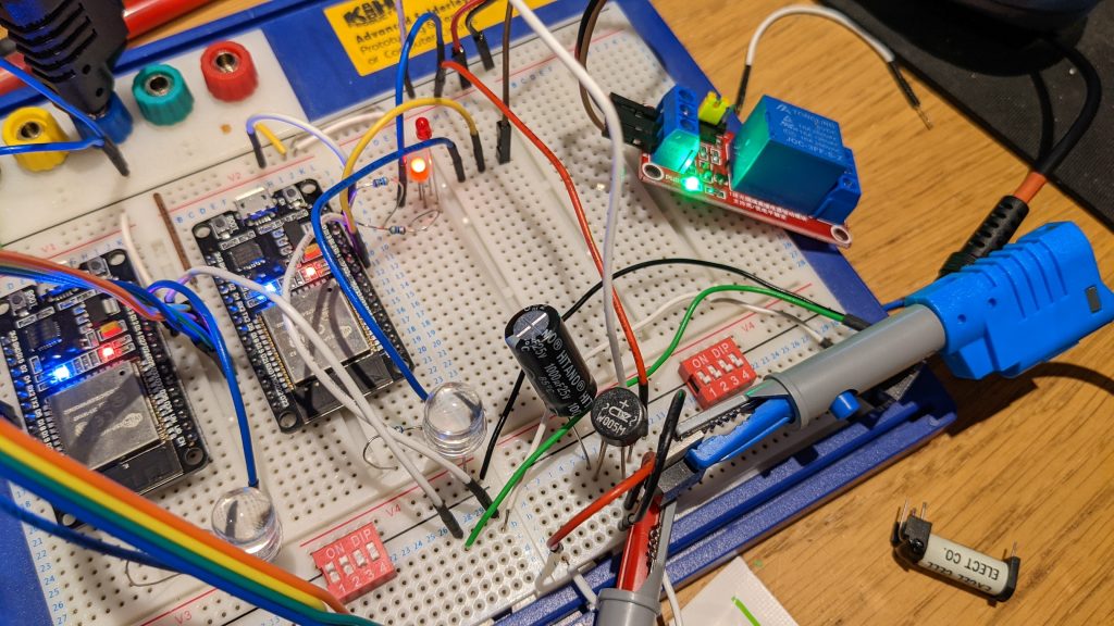
The image shows experiments with powering the controller from the doorbell transformer. The transformer has a quite high open circuit voltage, but also a very high internal resistance. The voltage would drop too low when the bell was rung to sustain the ESP32. I could prevent this by using a large power supply capacitor to keep the system running for the second or so, but this seemed unreliable.
The Pushbutton Circuit
The pushbutton, at time of writing, is not documented in the GitHub repository. It is a current mirror circuit using two transistors. This provides a steady 10mA to the button and the yellow LED which I fitted in place of the tungsten bulb. The LED glows when the button is not pressed, and the circuit sees the LED voltage drop of abotu 2V. This is converted to a logic level by a simple transistor circuit with quite high gain. The button press short circuits the LED so dropping the voltage to near enough 0V and extinguishing the light like a normal doorbell. This is detected by the transistor level shifter and fed to the ESP32 as a logic signal.
I feel that this circuit should be quite robust. It has not failed yet in about three years of continuous operation. It is also simple and fits the two wire installation of a normal doorbell.
The ringing and button are separate, policed by the microcontroller. This means that somebody at the door cannot hold our bell transformer and ringer coils engaged by leaning on the button. It rings for about half a second then releases.
In Conclusion
The doorbell has been in continuous use for over 3 years. The control boxes sit under the stairs and in the outbuilding’s garage, their little status LEDs blinking away to indicate connection. It rings twice when pressed, a bug which has now thanks to Claude Code been fixed in the repository. We like this feature though. We have no need to re-flash our doorbell but if we did we’d maybe implement ring patterns to bring back the double ring.
The code is at https://github.com/m0rjc/doorbell